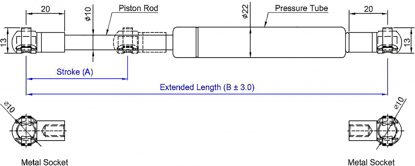
Unit:mm
9.8 Newton(N)=1 Kg=2.2 LBS
THE FOLLOWING SPECIFICATION ARE GERMANY STANDARD SIZE.
| Model No. |
Stroke
(A) |
Extended
Length (B) |
Force
Range (N) |
Weight (g) |
Remark |
| SB3-240-M920M8-XXXN |
70 |
240 |
100~1150N |
|
|
| SB3-270-M920M8-XXXN |
90 |
270 |
100~1150N |
|
|
| SB3-285-M920M8-XXXN |
100 |
285 |
100~1150N |
|
|
| SB3-330-M920M8-XXXN |
125 |
330 |
100~1150N |
|
|
| SB3-385-M920M8-XXXN |
150 |
385 |
100~1150N |
|
|
| SB3-405-M920M8-XXXN |
160 |
405 |
100~1150N |
|
|
| SB3-450-M920M8-XXXN |
180 |
450 |
100~1150N |
|
|
| SB3-485-M920M8-XXXN |
200 |
485 |
100~1150N |
|
|
| SB3-500-M920M8-XXXN |
210 |
500 |
100~1150N |
|
|
| SB3-525-M920M8-XXXN |
220 |
525 |
100~1150N |
|
|
| SB3-585-M920M8-XXXN |
250 |
585 |
100~1150N |
|
|
| SB3-670-M920M8-XXXN |
280 |
670 |
100~1150N |
|
|
| SB3-685-M920M8-XXXN |
300 |
685 |
100~1150N |
|
|
| SB3-700-M920M8-XXXN |
300 |
700 |
100~1150N |
|
|
| SB3-750-M920M8-XXXN |
330 |
750 |
100~1150N |
|
|
| SB3-785-M920M8-XXXN |
350 |
785 |
100~1150N |
|
|
| SB3-830-M920M8-XXXN |
370 |
830 |
100~1150N |
|
|
| SB3-885-M920M8-XXXN |
400 |
885 |
100~1150N |
|
|
Specification:
Rod Dia.: 10 mm
Tube Dia.: 22 mm
Rod Surface treatment : Nitrided Black
Tube Surface treatment : Black Coated
※ When you making enquiry ,please advise us the F1(Newton) force request.
Other size also available ,Please contact us for further information.
SUPERSEN-Gas Spring Free Series
Lifting, lowering, moving, adjusting
The gas spring can be designed with an approximately linear, progressive or degressive spring rate curve, to match the special request.
The characteristic curve of the spring describes the progression of the force of the gas spring over the stroke, from the extended to the compressed state and vice versa.
If the spring rate is flat and progresses in a practically linear manner, the force of the gas spring rises only slightly over the entire spring operation.
Spring rate: X=F2:F1
The force diagram on the left shows the line of the extension and compression force with a flat spring rate. The difference between the two lines is the result of the system friction produced during compression and extension.
The measuring points F1 and F4 are each located 5~10 mm before the fully extended and compressed stroke. The measurements were conducted at a temperature of 25℃±3℃.